Tesla!
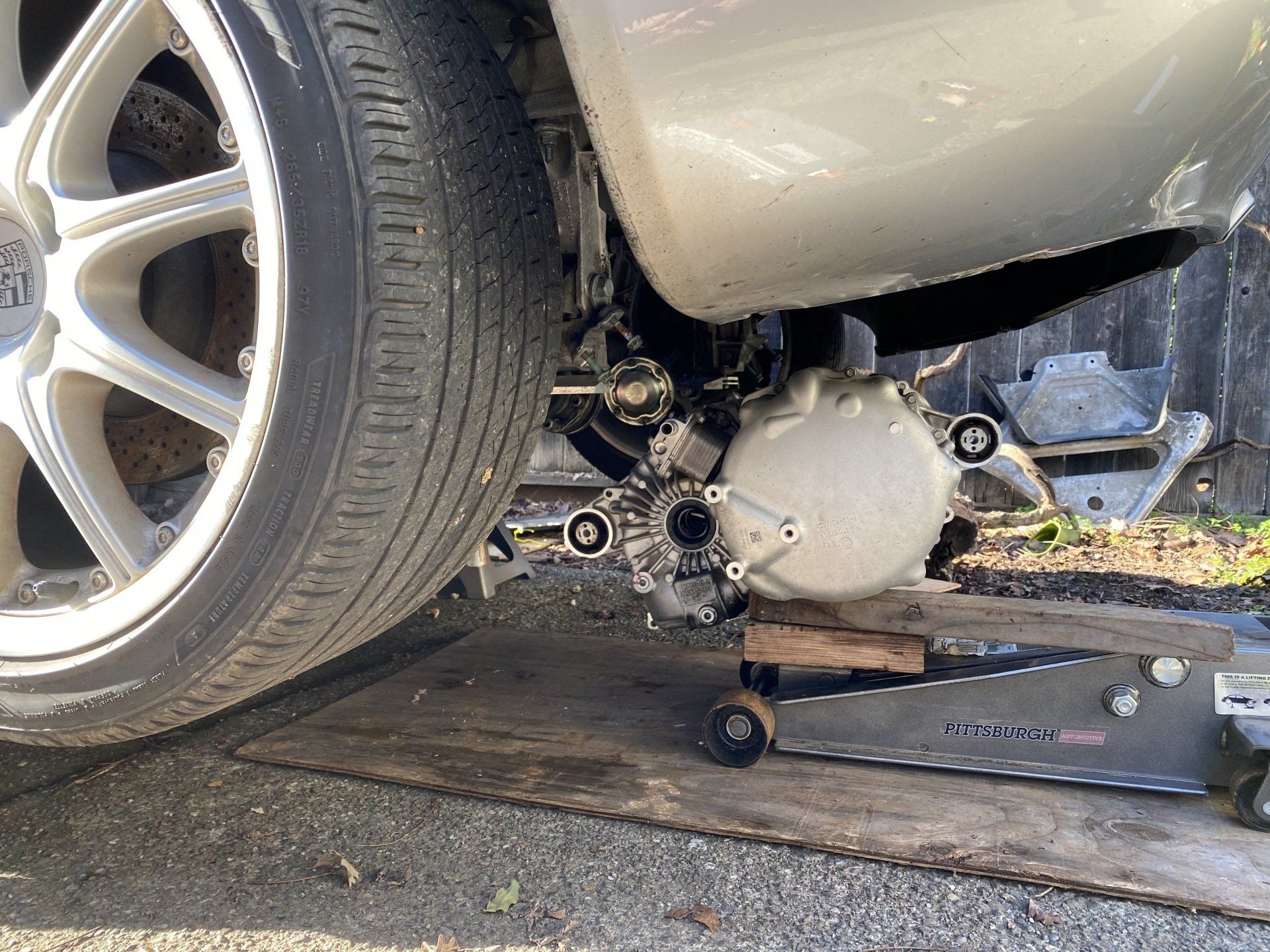
The Siemens motor is dead. Well, the output shaft anyway. Too many amps? The splined end broke off entirely. So this is a good excuse to upgrade to Tesla, with the amazing Openinverter board (that has my name on it, as I helped a little with the final design -- cool!).
Drove to Sacramento to get a rear drive unit from Calimotive. With the board, and then some half axles from Zero-EV (which will take a month to get here) I should be able to make this work.
Teensy + Chinesium
Electricity, of course, is the lifeblood of any EV, and the batteries are thus its most important component. They store thousands of watt-hours and can release hundreds of kilowatts at a moment’s notice. The ideal battery is light, powerful, safe, and cheap. Usually you can pick two, three if cost is really irrelevant.
So I got myself some Chrysler (Stellantis) Pacifica hybrid batteries. In the original vehicle, six modules are arranged in series to produce about 360 volts and 45 amp-hours, resulting in ~16KWh of usable energy in a package weighing 230 pounds. Two of these packs fit in the Boxster’s engine compartment alongside the motor, creating a 32-Kwh 360-volt battery pack weighing only 460 pounds. This is an excellent pack; not too expensive, and small enough to fit in nearly any vehicle without significant cutting.
Lithium batteries require care as well as feeding, in the shape of continual voltage and temperature monitoring. A typical EV pack consists of 96 cells in series with any number in parallel. Thus 96 voltages must be monitored continuously and accurately in order that no rapid unplanned disassembly occur, as that would be problematic. A system to watch all those cells is not inexpensive, with most running into the thousands of dollars for just 96 cells – and my specific configuration requires 192 monitors.
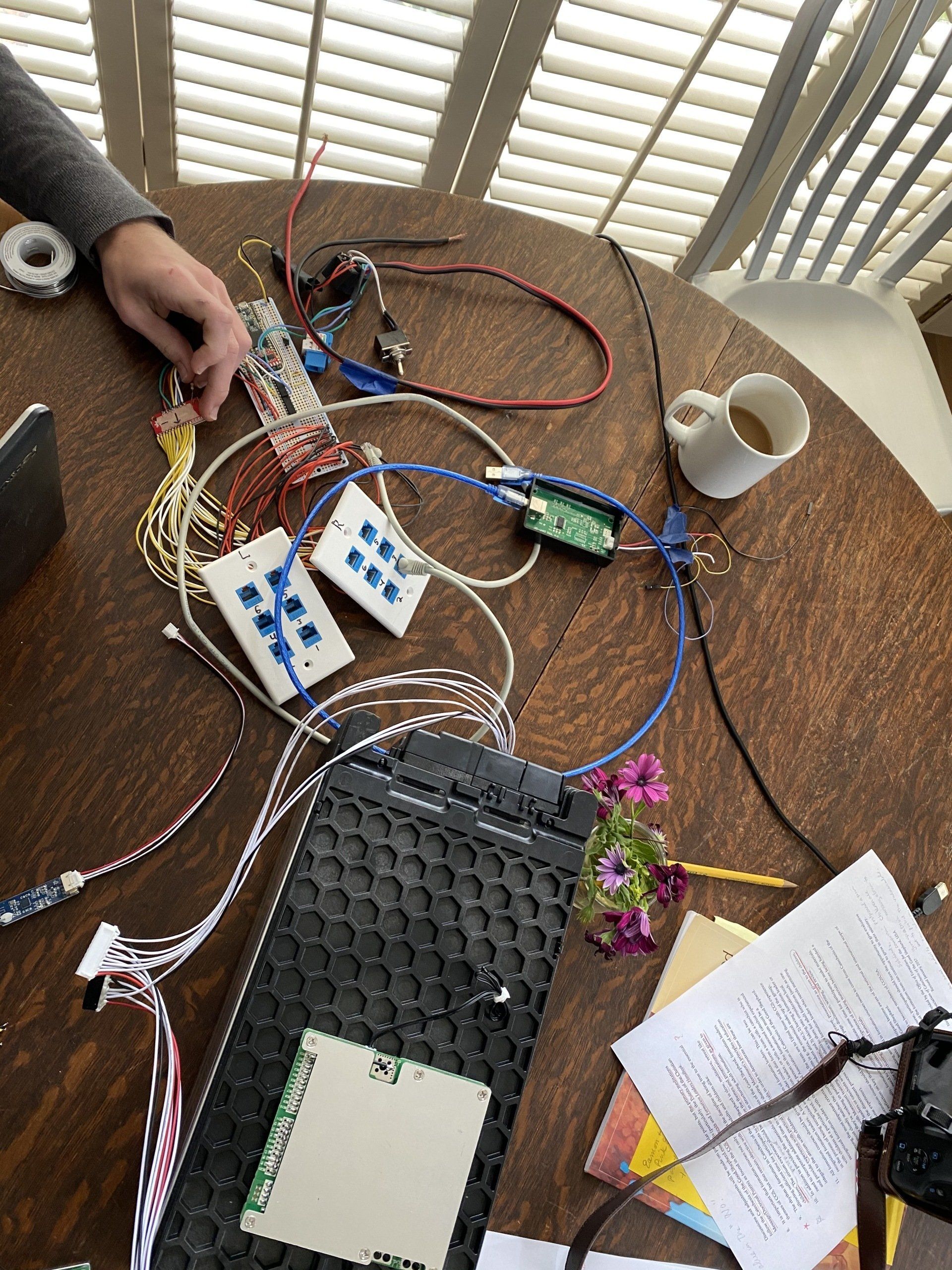
In search of a cheaper alternative, I discovered some ‘Smart E-bike 16S BMS modules’ from lithiumbatterypcb.com. These seemed capable of reporting cell voltages over Bluetooth to an app or over a serial link to any device.
I ordered 12 (only $450 or so) and used a Teensy 3.5 with a pair of multiplexers to communicate with all of them using a single serial port! (Isolators are also needed since each unit is grounded to the lowest cell it monitors. ADUM5241 have an internal isolated regulator – perfect.)
After significant testing and software shenanigans, I had a working monitoring system for all 192 individual cells which could communicate via CAN-bus with charger, quick charger, inverter, and the driver’s information display. And all for under $500! (Before zipties and hot glue).
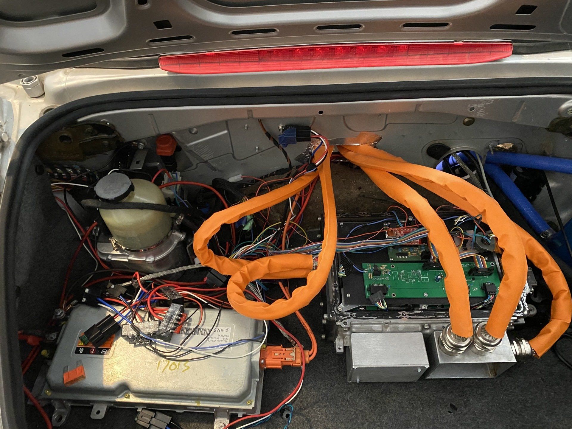
The batteries are contained in steel frames sided with 1/16 ABS, custom fabricated by Me and Dad Inc. Eight batteries sit inside the frames while the remaining four are sitting on top slightly skewed but still bolted in place. A 500A fuse sits inside a box along with five contactors (heavy-duty relays) which switch the power to the inverter and fast-charge system. The assembly is supported by four M12 bolts which together ought to be able to handle the 500 pounds of weight.
If you’re looking for some of these Pacifica batteries, you’re out of luck! It seems that LG Chem has cracked down on the resale of batteries from crashed vehicles. It’s really too bad; these are great cells, but the liability appears to be too much for the manufacturer.
So far there have been no false error messages and charging has worked beautifully over hundreds of miles.
TSM2500 + EVCC
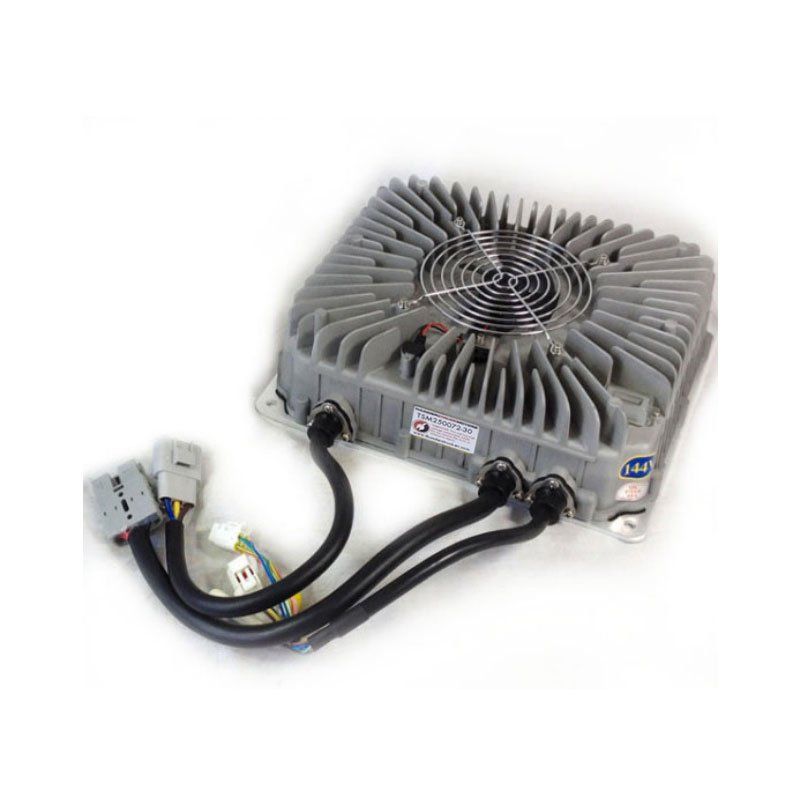
First of all: Thank you Thunderstruck! This is an excellent charger at an awesome price. The feature set is quite nice too.
The TSM-2500 is perfect for our requirements. With a 3Kw max, it's no fast charger, but this is basically a commuter EV so it'll do just fine. It is CAN-controlled so a clever little control box, called the EVCC (EV Charge Controller) is needed. J1772 support, multiple charging profiles, and even the ability to parallel chargers.
(Sorry to sound like a commercial, but this thing really is pretty awesome)
Thunderstruck is actually about 45 minutes away, in Santa Rosa, so we drove over one fine day and bought this charger and a DC-DC converter. That was a good day.
I got a 16A 120/240V EVSE. But since the charger can't detect input voltage, I had to make a voltage detector. I ended up using an old neon bulb voltage tester and some photoresistors. It's working great!
I'm using a 12v charger to keep the accessory battery topped off while charging the car.
The other day (January 1st) I got a new firmware file from Thunderstruck, as I've been working for them for some time. This new firmware adapted the charger to run at 500Kbps on the CAN bus instead of the old 250. This lets me connect all my CAN devices on the same bus instead of having to deal with a translator in the middle. Simplicity!
V2 Build Inverter
(With the V3 Build, this inverter is no longer needed. I'm using the inverter that comes with the Tesla motor.)
What is it?
To understand what the inverter does, you must first know how most EV motors work. While you may be familiar with the standard DC motor, which can be connected straight to batteries and spin by itself, the three-phase AC motor is a very different beast. It requires careful and precise switching of high voltage to create the right AC waveforms to make it spin.
The waveforms are calculated by a microcontroller based on feedback from a motor speed sensor and then sent to a power stage made of large insulated gate power transistors, or IGBTs. A power stage capable of 600 amps is standard in modern electric vehicles, with some manufacturers pushing for more power with larger transistors. The selection of controllers varies; some use multiple chips to handle different parts of the task (such as signal denoising and actual PWM output) while others use a single chip to do all the work, often with the use of internal timers to ease PWM generation.
What did I build?
The first controller I used in my car was an Azure Dynamics DMOC645, capable of up to 414A RMS at 400 volts. This controller was air-cooled since it was designed for a hybrid application in a truck, where it would not be in constant use and would have plenty of airflow. While it ran the motor smoothly, it began overheating and cutting power very quickly, and as an OEM component it did not lend itself to software modification.
I began, then, a significant regime of hacking. The first order of business was improving the cooling in that inverter by adding a liquid-cooling plate. This was accompanied by a hardware change, replacing the Azure control board with an OpenInverter board – an open-source solution for AC motor control, based on the STM32 platform and supporting nearly any AC motor with infinite room for customization.
OpenInverter turned out to have a rather steep learning curve, as usual for open source projects, and that resulted in a couple of rather large bangs as far too many amps flowed through IGBTs. By the time a new IGBT could arrive ($150… ouch) I had decided to completely replace the power stage with one from a Chevy Volt PHEV.
The Volt power stage is liquid cooled from the factory and incorporates not one, but two large MBB600 power modules. Each of these contains three half-bridge IGBTs capable of 650V and 600A continuously – and best of all, the two modules can be paralleled for a 1200A output! It’s also got a weaker power stage made to drive the original oil pump, which can be repurposed for use with an electric AC compressor.
To interface this power stage with my OpenInverter hardware, I purchased a PCB from a Slovenian gentleman by the name of Arber. His board conditions the current sensors and PWM signals for consumption by the STM32 and IGBTs respectively, and plugs into both easily with some added connectors. After some interesting soldering of 0805 resistors and SOT-23 op-amps, the electronics side was complete and the drivetrain was thus (mostly) ready to go. But it didn’t work – manual controls were functional but the motor ran away as soon as I tried to run it in closed-loop with sensor feedback. Why, you ask? I had the same question.
Electromagnetic interference, or EMI, is a huge concern in power systems, especially power systems with sensitive electronics or sensors where hundreds of amps might flow right next to a three-milliamp temperature sensor. My oscilloscope (a piece of garbage I got for $10) showed significant noise flying around the area, so I added braided shielding around the motor phase wires and the battery supply wiring. This reduced the apparent noise but didn’t solve the issue – the motor ran happily when I set a frequency, but if I asked it to calculate its own frequency from the desired speed it would run away to 10,000 RPM or so. With some more scoping of signal and power wires, I noticed that the encoder wires, which are monitored by the inverter to calculate motor RPM, would blank and stay at 5V once any power was applied to the motor. So I added an isolated power supply and a pair of optocouplers, allowing me to disconnect the ground and avoid any noise. With that, I hit the accelerator and the motor ran!
And now began a long process of tuning the inverter software, making hardware modifications, and test driving. The system as of last testing is operational but not reliable; it behaves in a different manner depending on which gear is selected (remember, this is still a manual transmission!). So if I tune for 1st gear and a good launch in that ratio, the car might be unable to start from a standstill in 3rd.
In the last round of upgrades I’ve replaced the original encoder cable with its unreliable twisting connector with some shielded CAT6 twisted pair and a simple DB9; with luck, this will still further reduce EMI and give more consistent behavior. Cooling changes have also been happening, as I have yet again relocated the radiator (back in its original position) and welded up a custom stainless reservoir.
Future plans in this segment include further software tuning for better consistency, some power improvements, and a more professional (and reliable) wiring scheme. If all goes well I will put the IGBT modules in parallel, doubling the available current and theoretically providing double the power – this would be breaking new ground and probably result in some release of smoke, we’ll see how it goes.
Leaf + Arduino
(This was my first BMS, for the original Leaf batteries. The code and info below will be useful if you are using Leaf batteries. My V2 Build has a completely different BMS.)
I spent hours looking for a cheap BMS. But every one would have cost over $1000 for the 96-cell Leaf battery. So I decided to use the original Leaf BMS, which clearly worked properly (else Nissan would never have used it.)
Here's the factory manuals. EVB.pdf is what you need for connector labeling and numbering.
http://www.nicoclub.com/FSM/Leaf/2014%20Leaf/
At a bare minimum, to balance cells and monitor them, you need Leaf Spy Pro, a Bluetooth OBDII adapter, and correct wiring.
Source: https://www.mynissanleaf.com/viewtopic.php?f=8&t=17470&start=20
Pins 12 and 7 to 12V, 2 and 14 to GND, 1 to CAN-HI, 13 to CAN-LO, and 6 shorted to 8.
The CAN and power also need to go to the OBDII adapter.
This will only get you battery data to an Android device running Leaf Spy. To use the pack safely, you must have some sort of high and low voltage cutoff for safety while charging and driving. So I got to work on some Arduino code.
Starting with a powerful Arduino-compatible board called the Teensy, I began looking at the CAN data coming out of the BMS. Fortunately some people have already decoded most of it, so I just had to figure out what went where. There was one irritating issue: Each frame has an index byte at the beginning, and that index rolls over after 16 frames. So when polling for cell voltages, I had to figure out some ridiculous logic to make it do what I wanted it to. Anyways, I got the code reading CAN data and converting it to cell voltages. However, although the BMS was communicating with Leaf Spy, none of the shunts were activating. Turns out there is an interlock switch, so pins 6 and 8 on the BMS have to be shorted. After that it jumped to life and began balancing cells. Since crimping and soldering another 104 wires didn't seem very nice, I re-wired everything with RJ45 (Ethernet) jacks. Now there will be 14 Ethernet cables connecting the BMS and batteries. I'm also using Ethernet cables to carry the CAN buses throughout the car, since they are durable and shielded and come with nice connectors pre-fitted and in many different lengths.
The BMS now communicates with the charger and IJLD505 (CHAdeMO controller.)
Parts
Nissan Leaf BMS - the one with one black connector and one gray one
Cheap Android tablet
Leaf Spy Pro
Teensy 3.5
CAN adapter - I used this clever little board https://www.tindie.com/products/Fusion/single-can-bus-adapter-for-teensy-35-36/